LC Series Inverters

Exeltech’s LC series inverter systems are equipped with 2KW power modules, this now provides double the output power within similar space requirements as are top selling MX series inverters. Modules are “hot” insertable, power levels are expandable, and modules can be added or replaced without interruption in power to your critical loads.
The LC system can be configured for power levels from 2 to 60KW single phase with 120Vac or 277Vac outputs. Up to 120KW at 240Vac bi-phase or 180KW at 208Vac or 480Vac three-phase with many input and output voltages also available.
A monitoring module plus any number of additional 2KW power modules combine to make a standard LC inverter. This type of system can be expanded as power requirements increase, and upgraded to be
N+1 redundant as desired. The LC system can be configured with Exeltech’s static transfer switch and maintenance bypass switch up to 20KW per phase. Also an optional customer interface cage with up to 5 DC breakers is available.
The LC system is extremely compact and lightweight. Power modules weigh only 9 lbs each and are equipped with LCD screens for quick access of system data.
Output voltage is precisely regulated, so that no measurable voltage change occurs on the output as input voltage fluctuates. Similarly, less than 0.5 volt change in output voltage will occur when the output load varies from 0 to 100% of rated power. With distortion of 2% maximum, this inverter offers the cleanest sine wave power available.N + 1 REDUNDANT
- EXPANDABLE
- REMOTE SWITCHING
- TRUE SINE WAVE
- “HOT” INSERTABLE
- 2000 WATT MODULES
- OPTIONAL SNMP
LC Series Module Overview
The LC Series inverters are a modular design and allows each system to be tailored for specific needs. Systems can range in output power, input voltage, redundancy, and a variety of other options. This is done by selecting different combinations of modules to create a LC inverter system.
The building blocks of the system are as follows:
-
- Power Module Cage Assembly
The cage assembly can be designed to accept DC input of either positive or negative. It will house from 1 to 6 inverter power modules resulting in a system output of up to 12,000 Watts. It will also house an optional monitoring module (recommended). The left most power module is the system’s master module. The next power module to the right is the system’s redundant (backup) master module. For redundant operation, the system MUST include a monitoring module. The monitoring module is required to initiate a transfer of control to the backup master module. - Power Modules
The power module is the backbone of the LC inverter system and is the majority of the modules in all systems. Each module is capable of producing 2000 Watts of continuous output power. Each module can perform all of the functions to operate as a system’s master module. The module will only perform the system master function when placed in the power module cage assembly location identified in the previous section. Each power module is equipped with an LCD display that can show power module status information as well as system status information. - Monitoring Module
The monitoring module provides a visual representation of different alarms created by the system. Each monitoring module has an ON/OFF switch for the system. If a monitoring module is not used the remote switch must be used to turn the system on and off. A monitoring module is required to detect a master power module failure and switch to the secondary master power module if it is available. There are a few different options available to monitor the LC inverter system.-
- Alarm Card:
With the alarm card, system monitoring is basic and is seen manually through power module LCD displays. Pre-set alarms (Alarm1/Minor & Alarm2/Major) are provided via dry form C relay contacts on the inverter systems back plane. Use of the other connections on the back plane may result in damage to the module or system. - Monitor Card:
With the monitor card, system data is more detailed and can be seen either manually through power module LCD displays or through Ethernet connection which allows for remote monitoring of system data. Each phase’s information can be reported via the Ethernet connection. The data can be sent to a PC to be viewed and logged or reported via SNMPv2 or an optional secure SNMPv3. Programmable alarms (Alarm1/Minor & Alarm2/Major) are provided via dry form C relay contacts on the inverter systems back plane. Product Status is used to program alarms (Alarm1/Minor & Alarm2/Major). Use of other connections on the back plane may result in damage to the module or system.
- Alarm Card:
-
- Power Module Cage Assembly

LC Series System Overview
The LC system can be configured from 2,000 to 12,000 Watts (1 to 6 power modules), with or without an optional monitoring module (highly recommended). With the monitoring module and a sufficient number of power modules, the system provides N+1 redundancy. See LC Product Guide.
Remote On/Off Switch:
A set of terminals are provided to turn the inverter system on and off from a remote location. The connection for the remote switch is on a remote alarm connector located under the rear access cover. Connect battery negative ‘Bat(-)’ to the ‘Sw1’ terminal to turn the inverter on. The maximum current in this connection is under 0.1 ADC, and has a maximum open circuit voltage of either 24, 48, or 108 VDC. An appropriately rated switch should be used. The remote switch and front panel switch are “OR’d” together so if either switch is on, the inverter system will turn on, and both must be off for shut down. When using the remote switch, insure the front panel switch is in the “OFF” position to control the inverter system with the remote switch.
Over Voltage Protection:
The inverter system will shutdown immediately if the DC voltage exceeds the set limits. When the voltage returns to the normal range, the inverter system will immediately restart. There is a small amount of hysteresis built into the over voltage turn off set point to avoid the possibility of turning off and on rapidly. An over voltage greater than 10% above the limit may cause damage.
Under Voltage Protection:
The inverter system will shutdown when the DC voltage goes below the set limit. The inverter system monitoring module will set an alarm when the inverter system reaches a voltage 5% above the low voltage set limit. When the voltage rises to approximately 15% above the low voltage set limit, the inverter system will turn back on and the alarm condition will clear.
Power Modules
DC Voltage Inputs:
24V, 48V, and 108V DC inputs are available. It is recommended to have a maximum ripple voltage of less than 5% with the peaks not going above Vmax and below Vmin.
AC Voltage Outputs:
120V and 277V AC outputs are available (+/- 6%) at 60Hz, (+/- 0.1%).
Load Sharing:
By control system design, the power modules will automatically load share current with other power modules. The load sharing occurs immediately when a module is either added or removed from a power module cage assembly. If a module fails for any reason, the remaining modules will immediately redistribute the load among themselves.
Cooling:
A microprocessor controlled variable speed fan is located on the face plate of the power module. The fan will operate when the module senses an appropriate combination of temperature and power. Fan speed is monitored, and reported to the inverter system monitoring module. Fan speed can be displayed on the power module’s LCD display.
Over Temperature Protection:
Each power module will go into thermal shutdown when its internal temperature exceeds the maximum set point. Approximately 5C prior to thermal shutdown, a warning alarm will be sent to the inverter system monitoring module, and will also be displayed on the power module’s LCD display. The power module will provide its full rated output up to the temperature listed in the specification sheet. Ambient temperatures in excess of the maximum specification will likely result in thermal shutdown unless the load is reduced appropriately (see detailed specifications for derating). When the power module shuts down, the alarm condition will persist and the cooling fans will continue to run. The power module will automatically restart when it has sufficiently cooled.
Overload/Short Circuit Protection:
If the load attempts to draw current in excess of this value, the output waveform will be “clipped” so that this limit is never exceeded.
The power module has a continuous output of 2000 Watts. In addition, the power module is also able to provide a 3 second surge of up to 4000 Watts (depending on the battery voltage and internal temperature). This surge current is available to supply the inrush current demanded by electronic or motor loads. If the surge persists for longer than 3 seconds, the waveform will be “clipped” in an attempt to reduce the output to under 2000 Watts. If “clipping” the waveform is ineffective in reducing the output below 2000 Watts (as would be the situation for an overload/short circuit condition), the power module will shut down after a period of about 7 seconds. Once shut down, it requires cycling the inverter system’s ON/OFF switch to reset from this condition. The cause of the overload/short circuit condition must be removed prior to cycling the ON/OFF switch, otherwise, the inverter system will shut down again after the 7 second delay.
Monitoring Module
- Alarm Card:
Alarm LEDs:
The alarm card will monitor and display different alarms from the system through the LED’s on the front panel.On/Off Switch:
The on/off switch is located on the front plate of the alarm card. It is used to turn the inverter system on and off.Relay Contacts for Alarms:
Dry relay contacts are available on the backplane to be used with pre set alarms (Alarm1/Minor & Alarm2/Major). - Monitor Card:
Alarm LEDs:
The monitor card will monitor and display different alarms from the system through the LED’s on the front panel.On/Off Switch:
The on/off switch is located on the front plate of the monitor card. It is used to turn the inverter system on and off.Relay Contacts for Alarms:
Dry relay contacts are available on the backplane to be used with programmable alarms (Alarm1/Minor & Alarm2/Major).Ethernet Monitoring:
An Ethernet port is available on the front panel to connect to a network for remote monitoring of the system. This includes the industry standard Modbus over Ethernet or SNMPv2 remote monitoring or an optional secure SNMPv3 connection.
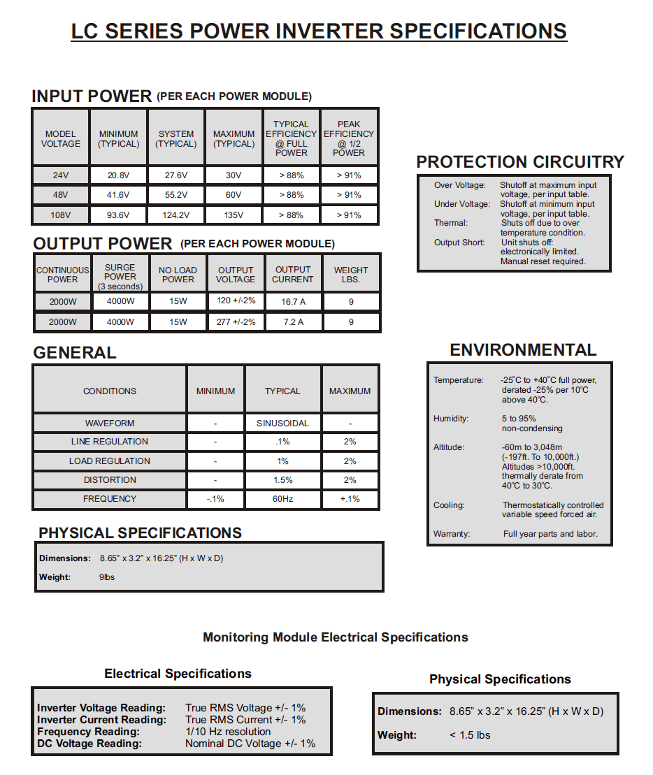
LC Series Inverter Specifications

LC Series Power Inverter Specifications

LC Series 12KW System Power Inverter Specifications
LC Systems Alarm Card
The alarm card can be added to 19” and 23” power module cages.
The alarm card is powered by the inverter or utility.
Each alarm card is specific to one input voltage.
AC & DC alarms only (Non-Programmable)
No data reporting through Ethernet.
Data can be monitored via power module LCD display.
Faceplate Displays:
INVERTER SWITCH:
Up is “ON” and Down is “OFF”
PHASE TEST BUTTONS:
Test the following functions for each phase:
-AC ALARMS
-AC LED STATUS
-MASTER TOGGLE
PHASE STATUS LED:
Will be green when AC power is in specs
DC STATUS LED:
Will be green when the DC power is in specs
LC Systems Monitor Card
It is now possible to monitor all of your remote power stations from a single location. You can have up to the minute verification that all of your remote power systems are 100% operational. For example, the remote power system can report that it is currently running at 90% of its rated capacity.
Operation
Normal operation of the monitor card is similar to the alarm card previously described in this document. The biggest difference is the remote monitoring of the system data.
Remote Monitoring
Ethernet connection allows for remote monitoring of system data. Each phase’s information can be reported via an Ethernet connection. The data can be sent to a PC to be viewed and logged or reported via SNMPv2 or an optional secure SNMPv3. Programmable alarms (Alarm1/Minor & Alarm2/Major) are provided via dry form C relay contacts. Use of the other alarm ports on the back plane may result in damage to the module or system.
Differences from Alarm Card:
-Remote data monitoring
-Not limited to a specific input voltage
-Allows for programmable alarms
-Built in microprocessor that allows for a wider
range of system data. Data can be monitored both
remotely and via power module LCD display
Faceplate Displays:
INVERTER SWITCH:
Up is “ON” and down is “OFF”
PHASE STATUS LED:
Will be green when AC power is in specs
COMM STATUS:
Will be green when monitor card is communicating to another device
IP RESET:
When pushed it will Reboot the communication port
Ethernet Port:
Allows connection to the inverter system via Ethernet cable
LC Series Part Numbering System

LC Series Part Numbering System
Data Sheet
LC Series

The Most Trusted Provider
of Inverters Worldwide!
Links
Headquarters
7317 Jack Newell Blvd N
Fort Worth, TX 76118
Phone: 800-886-4683
Phone: 817-595-4969
Fax: 817-595-1290