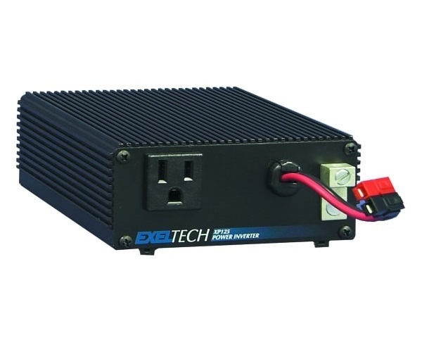
125 Watt (XP Series)
Pure Sine Wave Power Inverter

XP Series Inverters
Exeltech’s XP series inverters provide the cleanest, best regulated sine wave output over the widest DC input of any inverter on the market today. They are extremely low in Total Distortion—specified to 2%, and typically better than 1.5%. Total Harmonic Distortion is typically 0.8% to 0.9%. Remaining distortion is a result of residual switching noise, which amounts to a very clean 25 KHZ sine wave superimposed on the fundamental output. No significant harmonics of 25 KHZ exist. This spectral purity will exist over the inverter’s entire operating envelope, including non-linear and reactive loads. As long as peak output current remains less than 300% of rated current, total harmonic distortion will remain within the 2% spec. Peak current capability of the inverter is key to understanding its operational envelope. As long as the inverter is supplying less than this amount, it will function properly and operate virtually any load.
Many inverters are rated in Volt-Amps (VA), as opposed to Watts. This is in an attempt to make an inverter or UPS (Uninterruptible Power Supply) appear larger than it really is. The only fair way to specify these products is in Watts (W), which is power the inverter can actually deliver. If Exeltech inverters were specified in VA, Our 1100 Watt inverter could be rated at 1375 VA at .8 power factor, 1570 VA @ .7 pf, or an incredible 2200 VA @ .5 pf. It is confusing to specify a product in VA, because the power factor must also be specified. Exeltech’s XP-Series inverters can output their full rated power continuously at 30 C° (86 F).
The inverter can maintain a spectrally pure output with any load, due to a specially designed non-linear control loop in the primary DC to DC converter. This circuitry is one of three circuits that protects the inverter from any overload condition.
XP-125 Inverters
XP-125 Inverters are capable of exceeding their rated power by 10% for a limited time. The inverter’s capability at this level is primarily dependent on temperature. If output power is exceeded, output voltage is reduced to a level that will provide the inverter’s rated power to the load by clipping tops of the waveform. The inverter can indefinitely and safely operate in this mode. Should the overload condition clear, the inverter will again provide the cleanest Sine Wave in the industry.
XP-125 Standard Features
DC INPUTS (12 VDC – 108 VDC): A 3′ non-terminated, two conductor power cord is provided. Insulation on the negative (-) conductor is black and insulation on the positive (+) conductor is red.
AC OUTPUTS: One NEMA-15 outlet (standard wall receptacle) is located on the Front Panel.
LOW BATT/THERM BUZZER: Produces an audible alarm if DC input voltage falls to a level within 2% to 4% of the low limit of inverter, or if there is an over-temperature condition.
OVER VOLTAGE PROTECTION: If input voltage exceeds set limits, the inverter will immediately shut off, without warning. When input voltage returns to normal range, it will immediately restart. Since high over-voltages tend to have very fast edges, the inverter must shut down quickly to protect itself. This kind of fault usually occurs if the battery is suddenly disconnected from the system and the battery charger continues to supply current.
UNDER VOLTAGE PROTECTION: When battery voltage falls to within 2% to 4% of low line voltage, the LOW BATT/THERM buzzer will sound. If the condition continues without reducing load to the inverter or adding charge to the battery, the inverter will shut off. When voltage rises to approximately 95% of nominal battery voltage, it will turn back on and the alarm condition will clear.
OVER TEMPERATURE PROTECTION: The inverter is also protected against overheating. It will provide its full rated output up to the temperature listed in the specification sheet. If it is subjected to higher ambient temperatures or air circulation is blocked, the inverter could overheat. If the LOWBATT/THERM buzzer sounds, immediate action is required or the inverter will shut down. Either reduce load, or provide more cooling in the immediate environment. If no action is taken, the inverter will likely shut down within two minutes. When the inverter shuts down, the alarm condition will persist.
Since the inverter has eliminated its load, it will quickly cool. It will automatically restart when it has sufficiently cooled, and the LOWBATT/THERM alarm will clear. A warning buzz will occur 5 C before shut off. If output power is exceeded, output voltage is reduced to a level that will provide the inverter’s rated power to the load by clipping tops of the waveform. The inverter can indefinitely and safely operate in this mode . The overpower protection circuit will recover instantly when the overpower condition clears.
XP-125 Accessories
2U (3.50″) x 19″ relay rack mount face plate (mounts 1 XP125 inverter)
photo | 020-00138-404
2U (3.50″) x 19″ relay rack mount face plate (mounts up to 3 XP125 inverters)
photo | 020-00123-401
2U (3.50″) x 23″ relay rack mount face plate (mounts 1 XP125 inverter)
photo / 020-00137-402
2U (3.50″) x 23″ relay rack mount face plate (mounts up to 4 XP125 inverters)
photo / 020-00124-400
XP125 surface mount bracket (requires 2 per unit)
020-00131-400
Data Sheet

XP Series
Product Manual

XP 125

The Most Trusted Provider
of Inverters Worldwide!
Links
Headquarters
7317 Jack Newell Blvd N
Fort Worth, TX 76118
Phone: 800-886-4683
Phone: 817-595-4969
Fax: 817-595-1290